
The amount of light an individual receives during the day drastically affects one’s mental health and well-being. Statistics show that those who work in higher-lit areas such as workspaces with lots of windows are more likely to work more efficiently and are happier than workers who don’t. Have you ever noticed that you feel a little sadder during the colder months? This phenomenon is a real scientific disorder called ‘seasonal affective disorder’ (SAD). Scientific proof shows that the more time we spend in low or artificially-lit areas, the higher risk there is to our overall health. So, it is essential to know if you are receiving the right amount of natural sunlight, especially in your maker labs, whether this is on your dining room table or garage.
To make sure we are all getting the right amount of sunlight, here at Pokit we have decided why not build something easy that anyone could make with an Arduino and Pokit Meter. We took some inspiration from Dcamino’s project but made some minor tweaks to work with Pokit Meter’s data logger.
We’ve also created a short video for you to follow along here.
What you need:
- 1 x Pokit Meter
- 1 x Arduino and cable connector
- 1 x Light Dependent Resistor (LDR)
- 1 x 10k Ω Resistor
- 8 male to male leads
- 4 shorter leads
- 3 longer leads
- 1 x Power source and cable connector
These can be found using the links below:
Building the Light Sensor
- Connecting your resistors
Pin your light dependent resistor to the middle of your breadboard. Pin your 10k Ω resistor next to the light dependent resistor thus connecting the two resistors in series.
- Connecting the leads and wiring
In this project, you are essentially using the Arduino as a power supply while Pokit Meter is being used for logging the light sensor data. Follow the schematic below to start connecting the wires.
Once finished, connect the power cables to the Arduino and connect a power source.
- Connecting your Pokit Meter
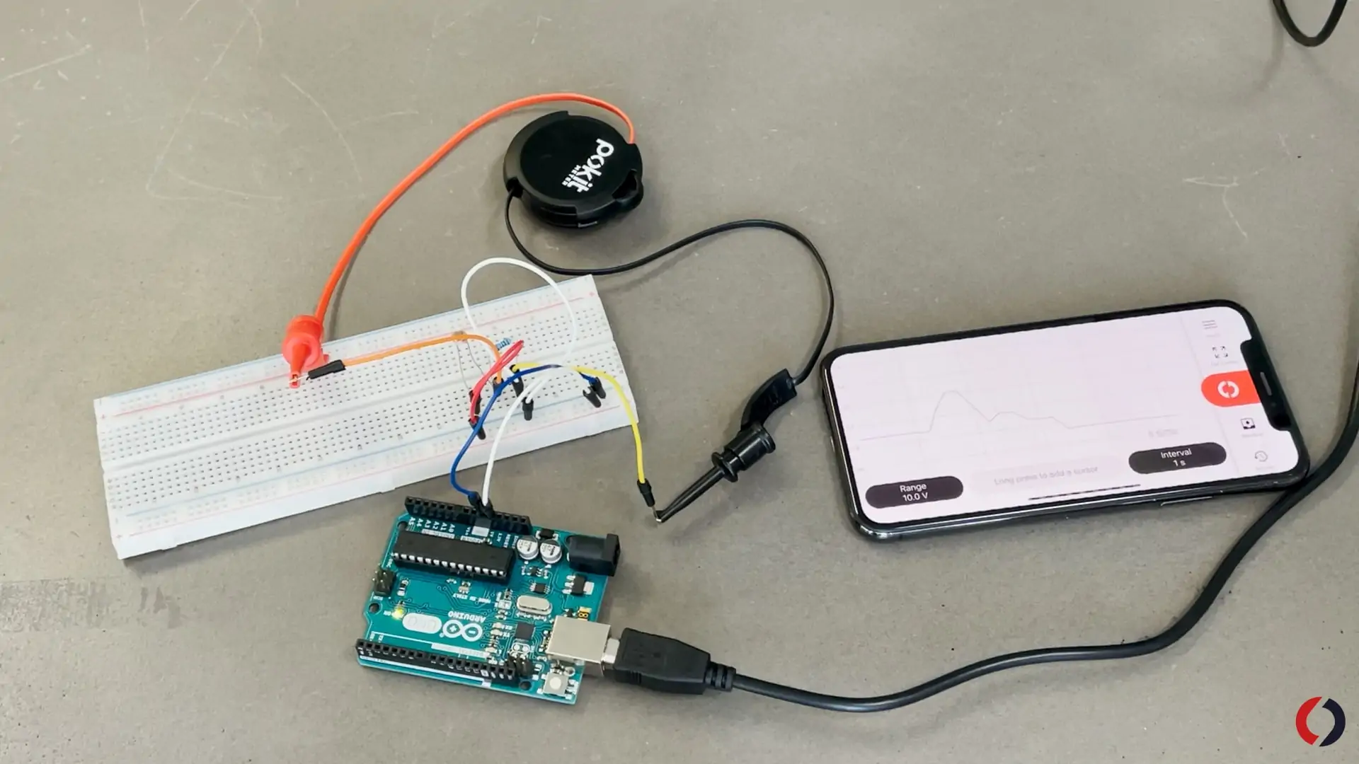
To connect the Pokit Meter, use the cables that have been left un-pinned to the Arduino and breadboard. Using these cables, you’ll be able to connect your Pokit Meter with the wire grips. Select the logger function on your Pokit Meter and you should be able to acquire and log the lighting in your area. For logging, it is best to set your parameters at around 5 to 10V and acquire a signal every 1 minute.
Here’s an example of the log we did in the Pokit Office.
You’re done but what does it all mean?
Well, it has been found through a study by Coloration Technology that whilst working in an office, the most appropriate lighting to work efficiently is 500 lux. So, we tested our LDR sensor against a Light Meter, so you can interpret the data the LDR is outputting.
| Voltage (V) | Lux (lx) |
| 0 – 0.9V | 0 – 99 lx |
| 1 – 2 V | 100 – 599 lx |
| 2.1 – 3 V | 600 – 999 lx |
| 3.1 – 4V | 1000 – 2050 lx |
| 4.1 – 5 V | 2051 – 5000 lx |
We found that we get around 700 lx in lighting here in the Pokit Innovations office because of the large windows (office tour anyone?). If you end up making your own Arduino LDR Sensor, tag us on Instagram or Facebook @pokit.innovations.